Safety Pole Introduction and Installation Videos in English and Spanish
Introduction
Play Video
English Installation
Play Video
Spanish Installation
Play Video
Safety Pole Tech Specs & Installation Guide
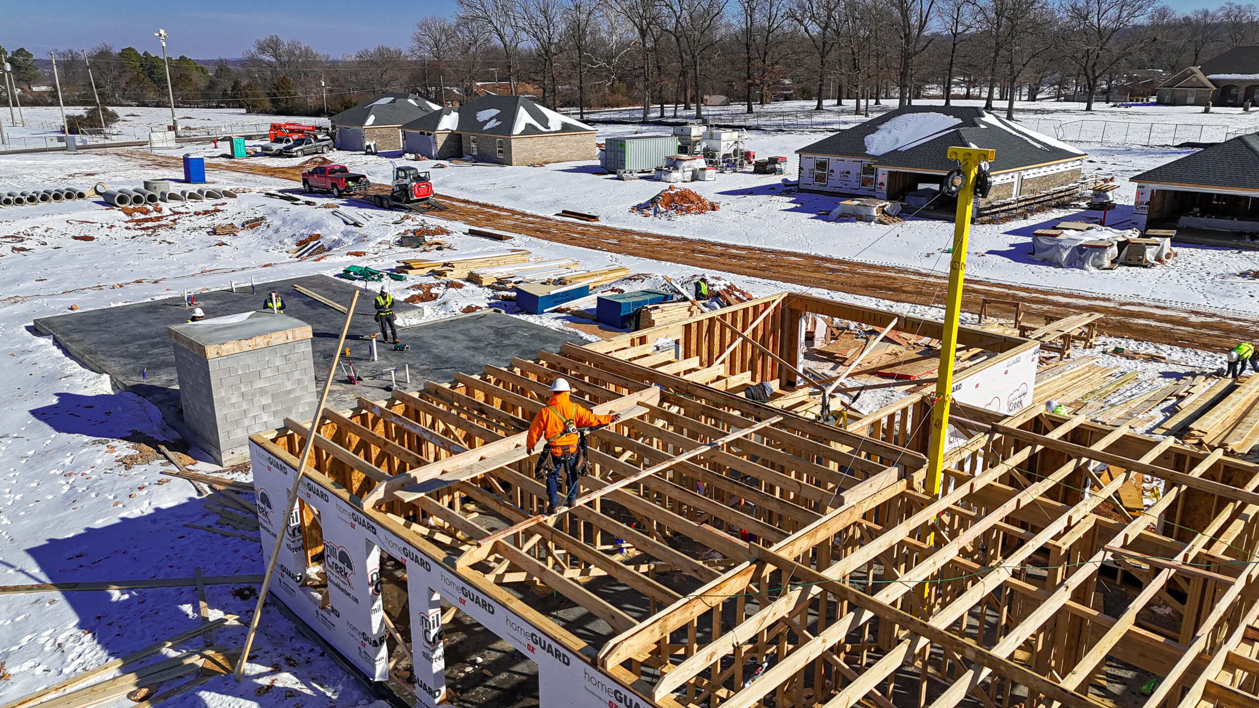
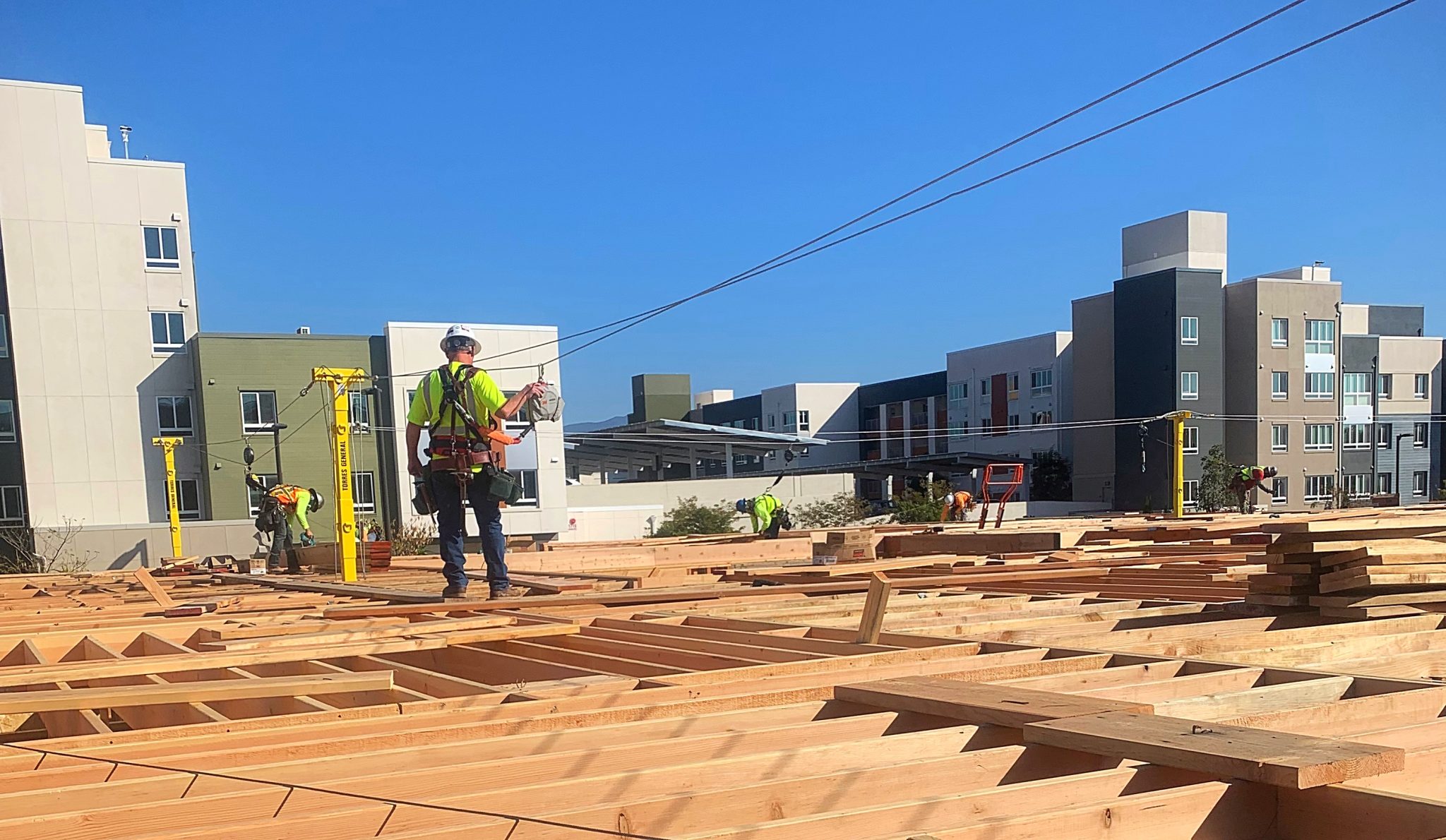
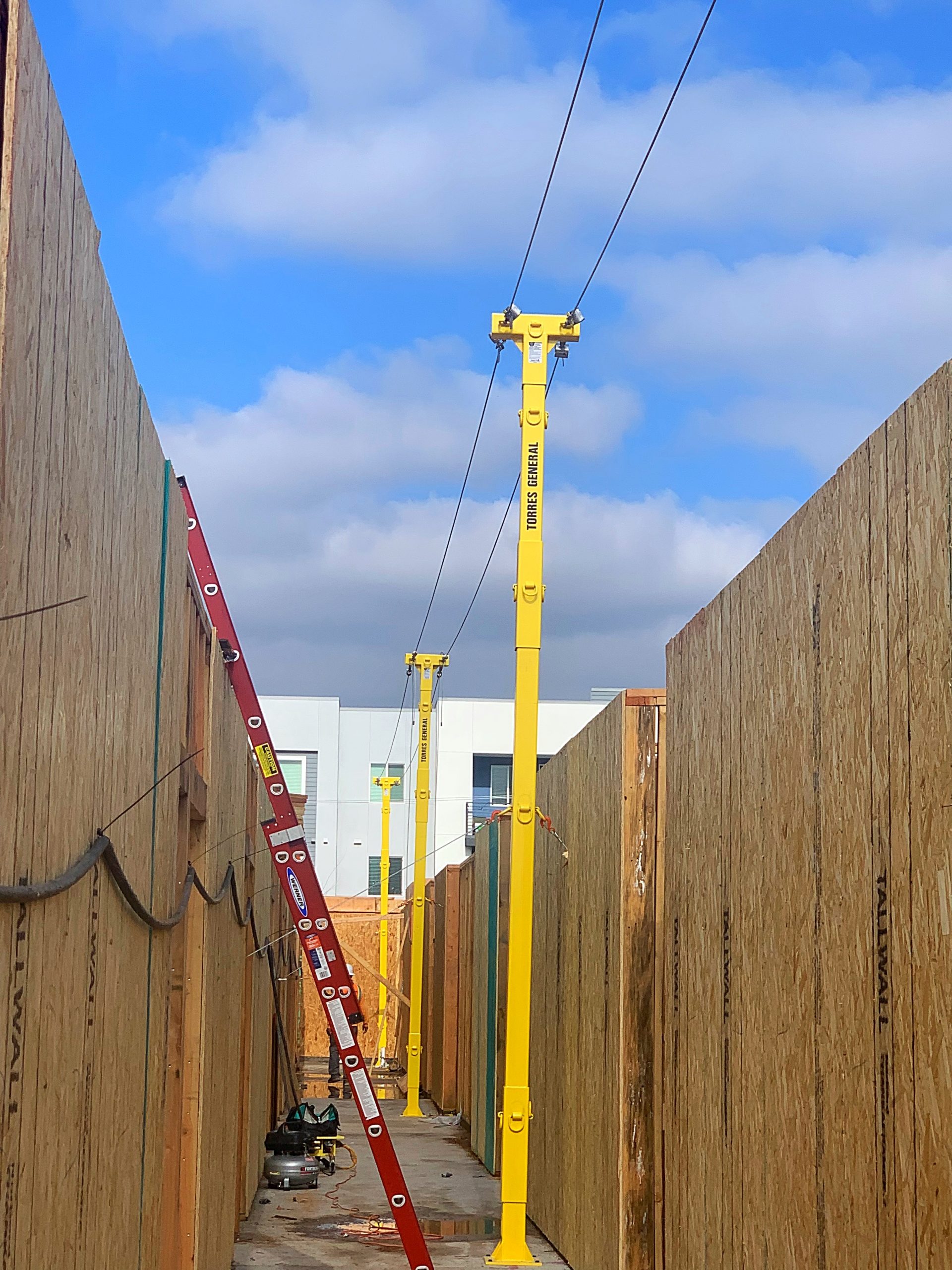
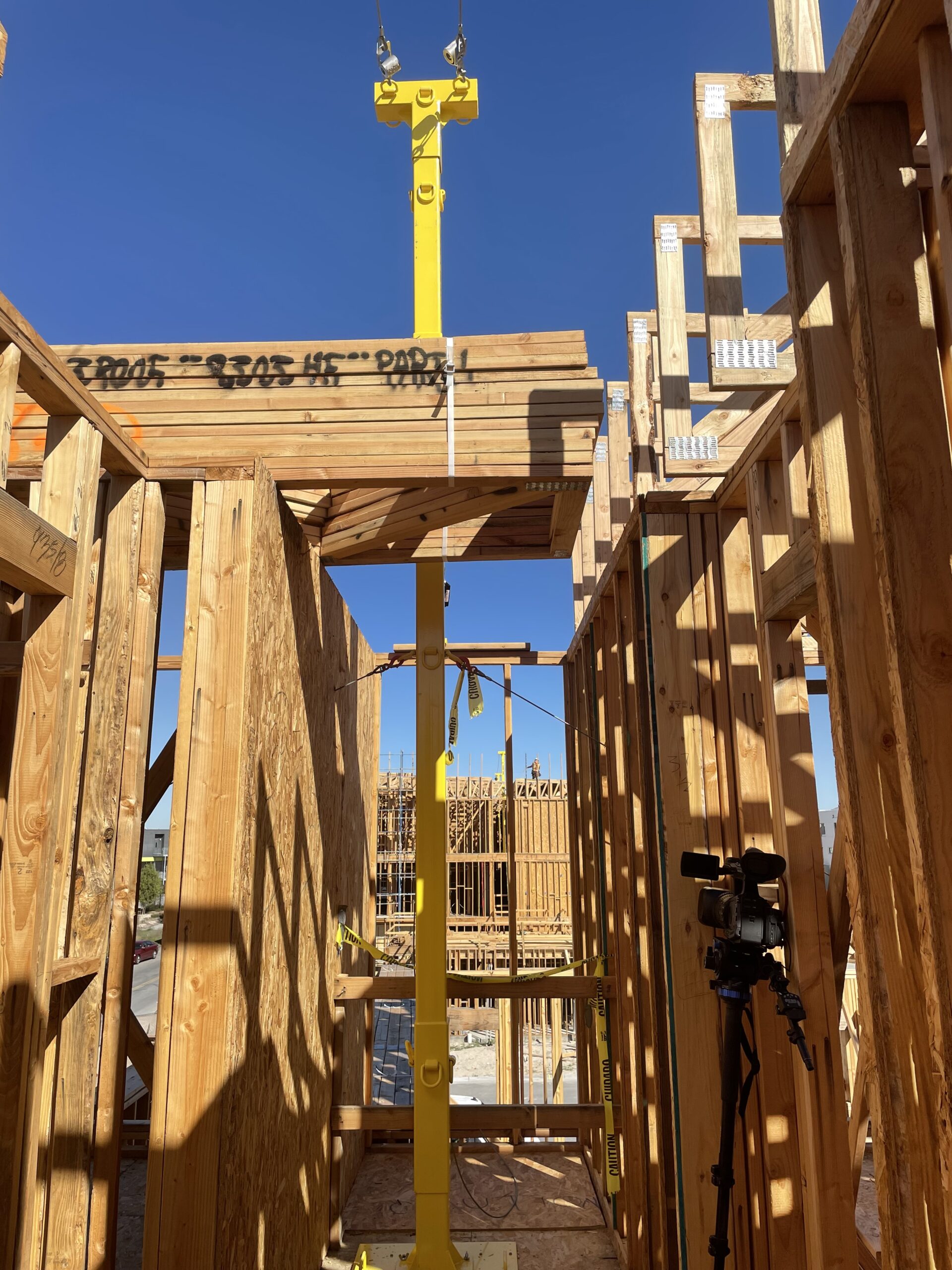
The Safety Pole System can be used as either a single pole anchoring point or as a Horizontal Lifeline (HLL) system during the framing of residential or commercial construction.
Components of a Single Safety Pole System
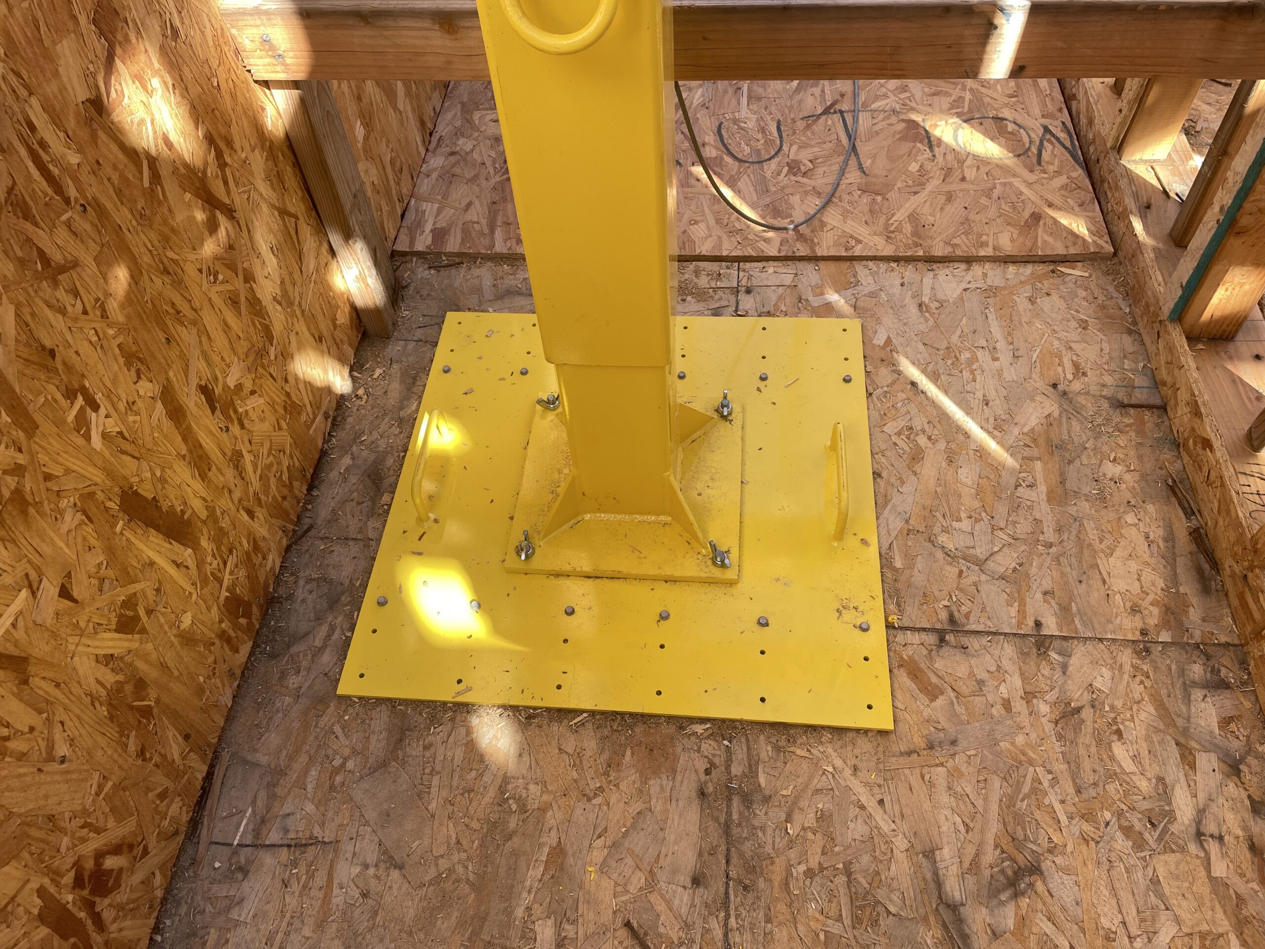
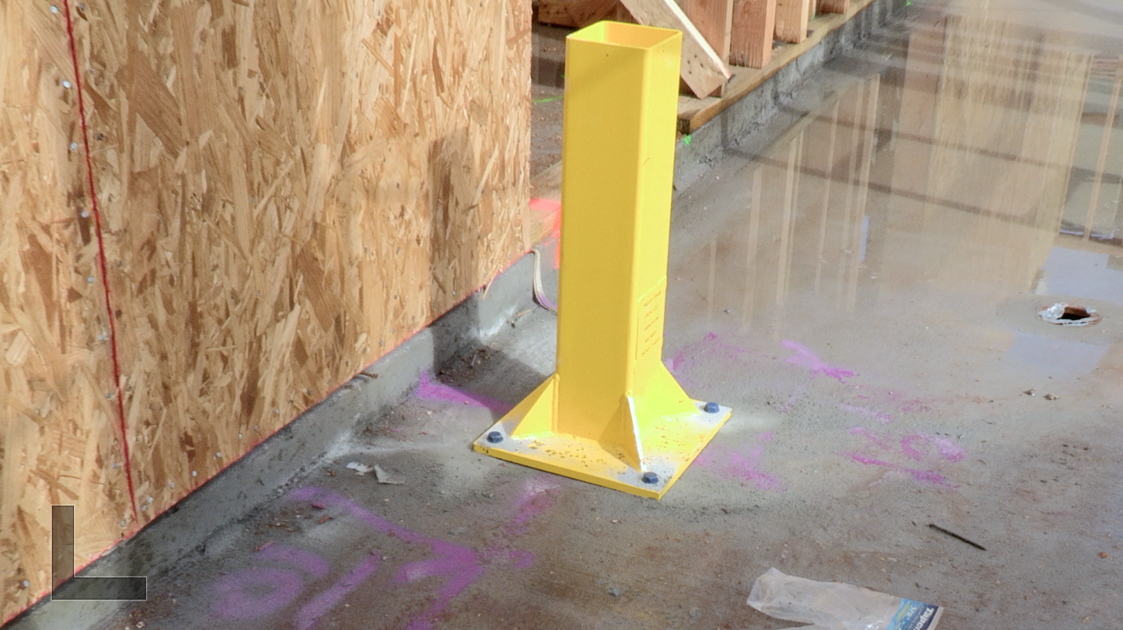
Base: Each system comes with two Bases. The Base is installed with 1⁄2” x 4” concrete anchor bolts. Through the Base Screw Ports, drill 1/2” in diameter by 3.5” deep into the concrete foundation.
10’-Section: Each system comes with 10’-Sections to give a max pole height of 27’. The 10’-Section can be stacked on top of each other to increase the pole heights.
5’-Section- each system comes with x2 5’-Sections. You can stack 5’-Sections to replace the 10’-Sections to reach the required pole height of 17’-6”
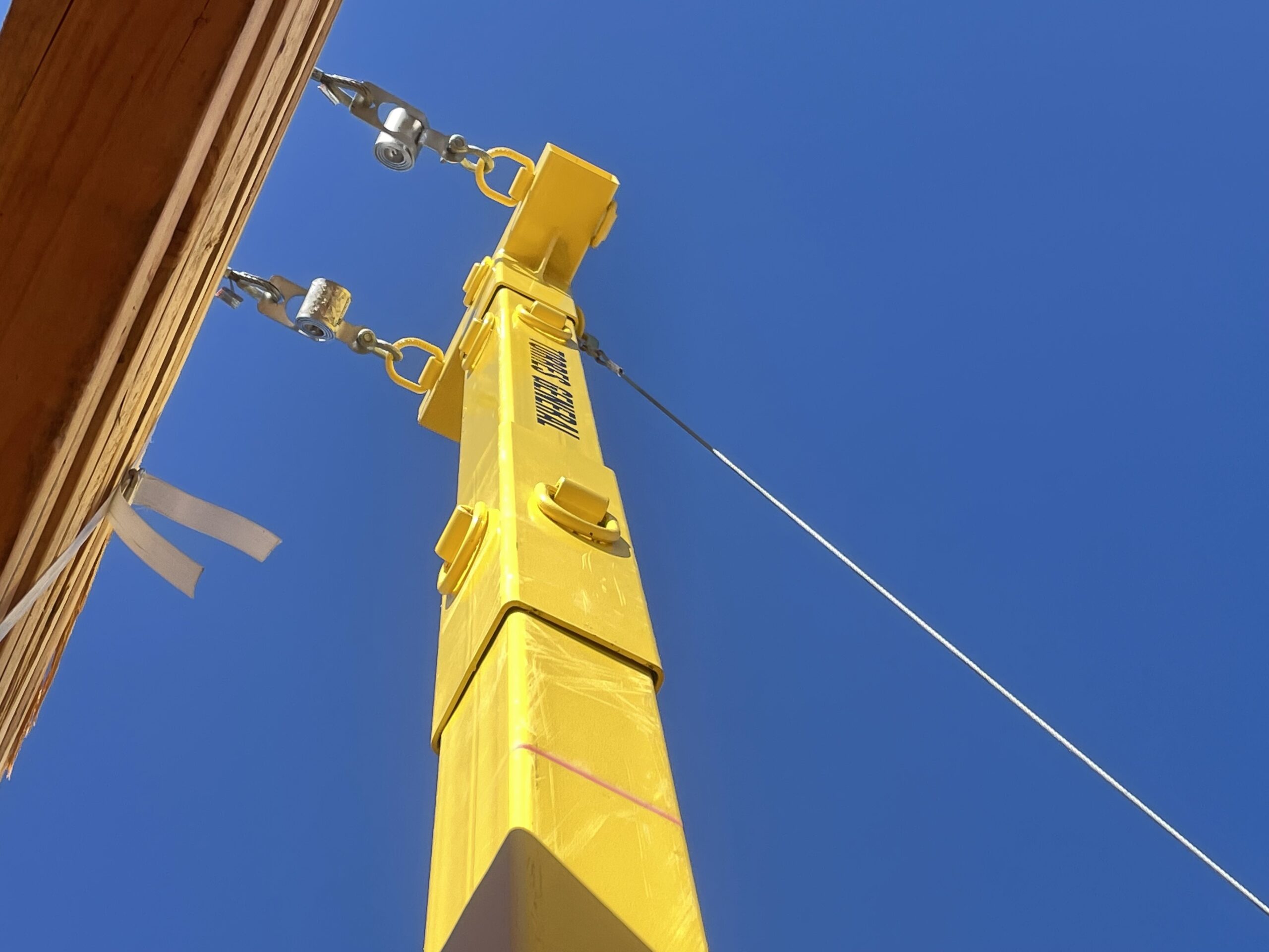
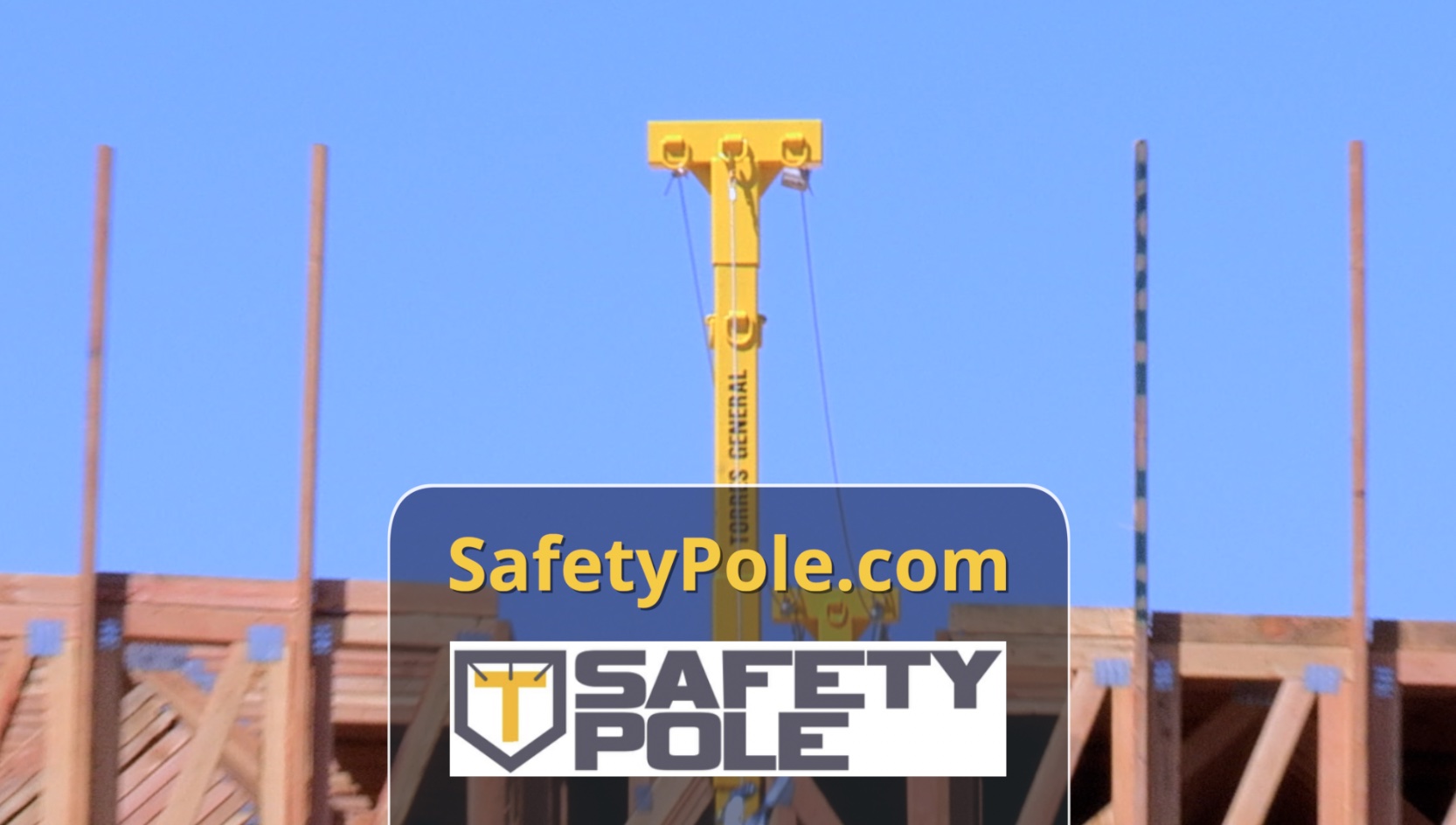
T-Section: there are x2 T-Sections for each system. The Horizontal Lifelines connect on the outer D-Rings of the T Section.
Shoes: Each system comes with x6 2×6 Shoes. The system shoes connect to a 2×6 exterior bottom plate or they connect to a 2×4 interior sil-plate with studs.
Tie-Back Cables: There are x6 Tie-Back cables customized to any length needed. Tie-Back cables can be combined for additional length to reach the Puller’s pulley hook.
Pullers: Each System comes with x6 Pullers.
Optional: Raised Floor Plate- The Raised Floor Plate is an adapter plate that allows the system’s Base to be mounted on the wood subfloor.
QR Coding: Each System comes with a QR Code linked directly to the Safety Pole YouTube Channel which allows the framer to view the installation video in both English and Spanish right on their smartphone.
Training: Safety Pole provides initial Installation Training for personnel who will be deemed competent in installing the system.
Customization: The Safety Pole System can be custom powder coated to any color desired and a company decal can be added to the system.
Weight of the Components for the Safety Pole System
Timelapse Installation
Play Video
Animated Installation
Play Video
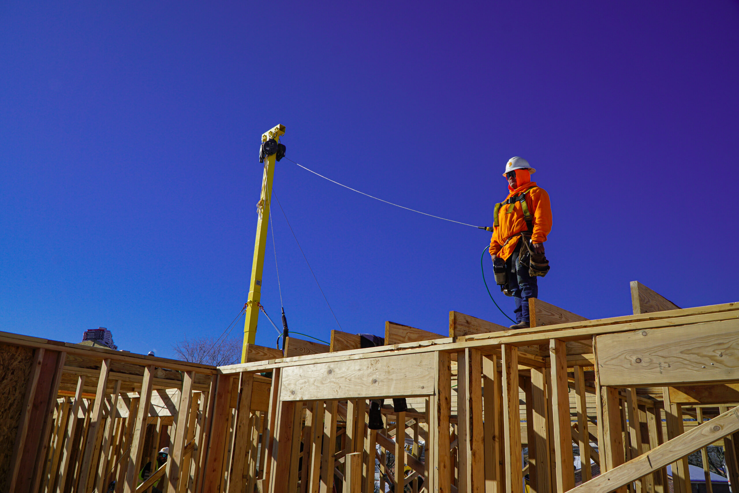
Single Anchor Point Safety Pole System
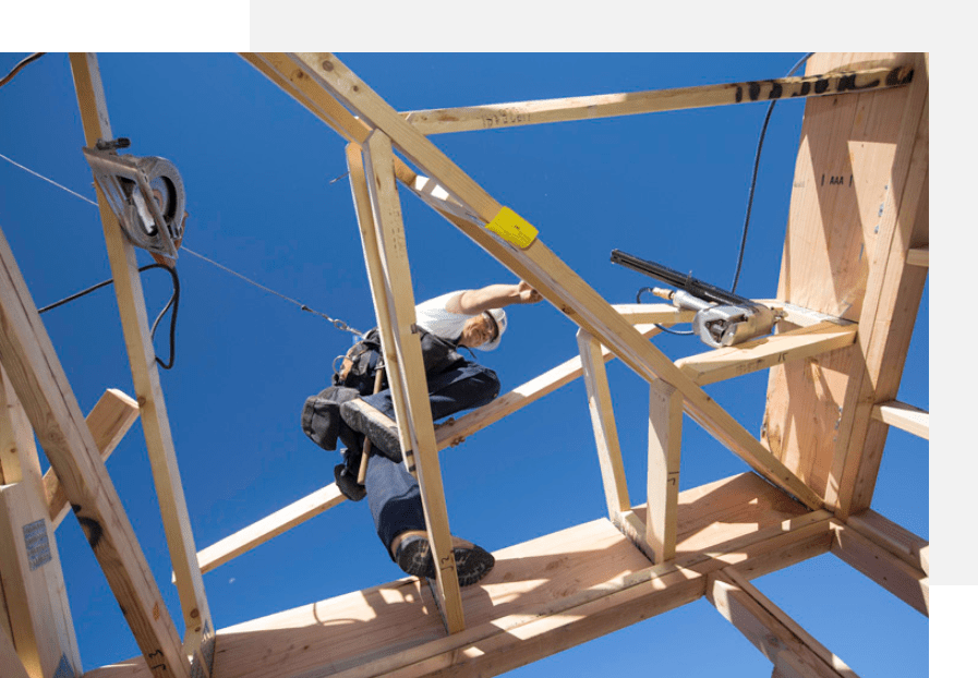
As a single anchoring point system, the System can accommodate up to 4 workers. The worker’s Class 1 or 2 SRL connects directly to the D-Ring on the T-Section. Be sure to connect the SRL to each outer D-Ring on the T-Section when using 4 workers..
Have four Tie-Back Cables on each of the 8’ D-Rings on the 10’-Section connecting to the 2×6 shoe that hooks onto a 2×6 exterior bottom plate or a 2×4 interior sil plate with studs
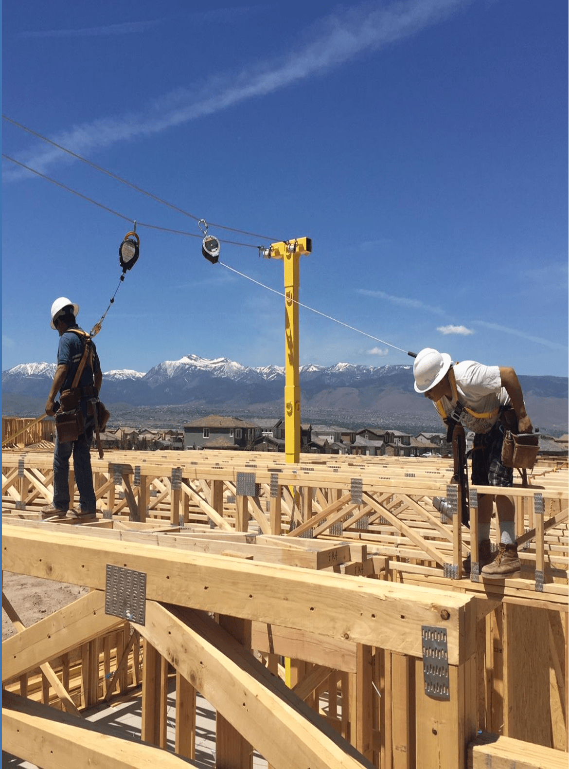
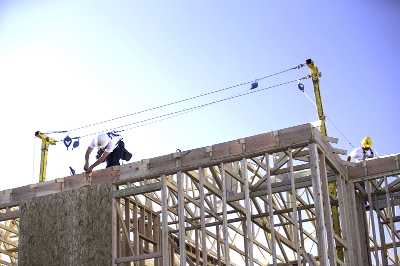
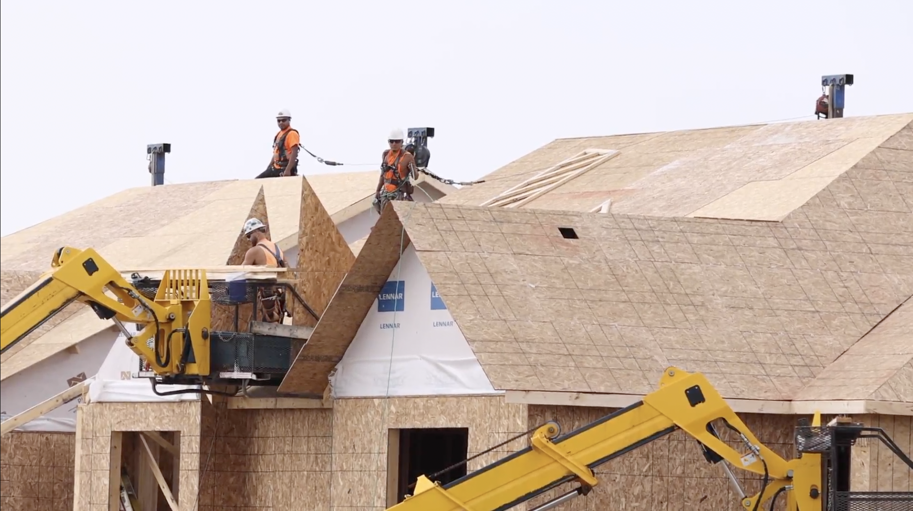
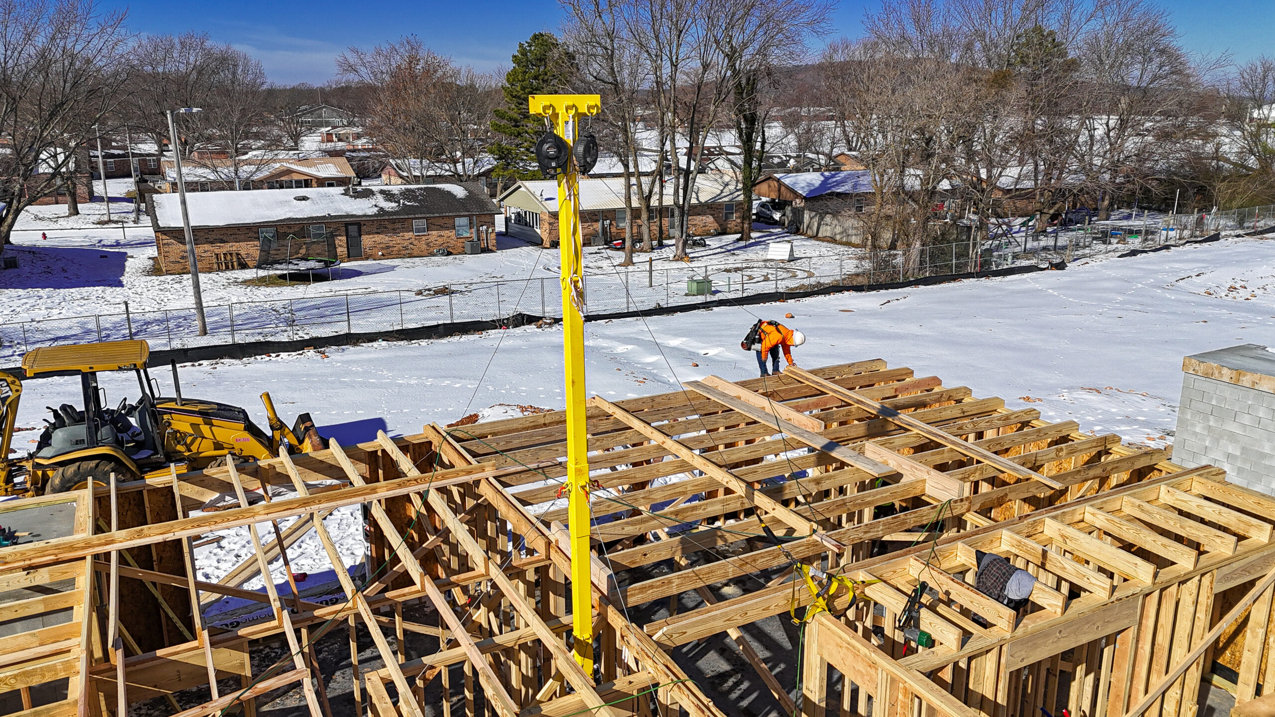
Horizontal Lifelines
The maximum horizontal lifeline span is 60 feet. The system length can be extended by using multiple pole spans.
As a Horizontal Lifeline System, the System can span a maximum of 60’ and accommodate 2 workers per Horizontal Lifeline or 4 workers per span. You can tie off an additional worker to the backside of the end pole if needed.
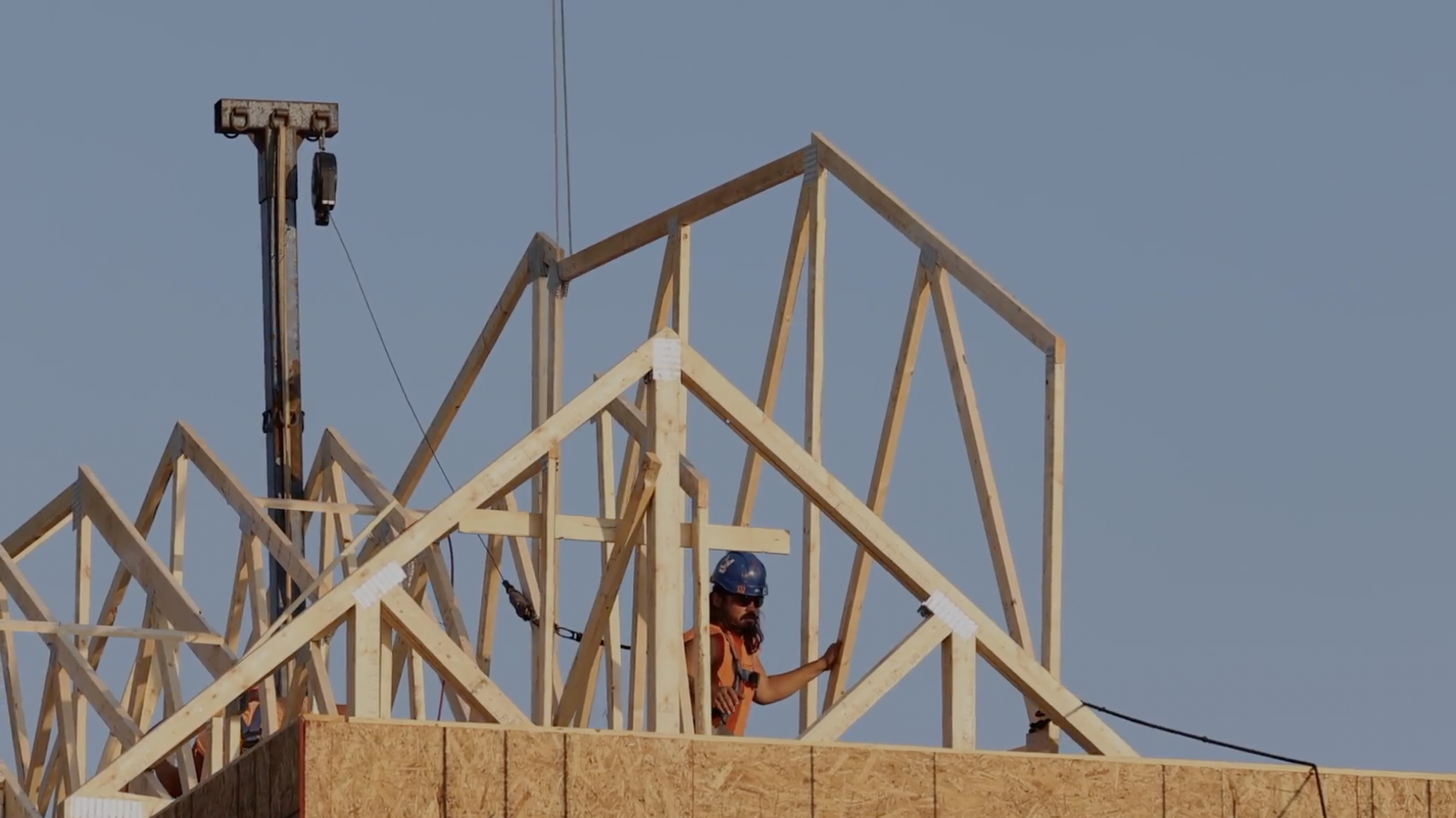
Safety Pole is a Modular System
The system traditionally sets Base, 10’-Section, 5’-Section, and T-Section to get the max system height to 17’-6”
Due to taller wall heights, the System can be configured to set the Base, x2-10’ Sections, and a T Section.
The Max height on a single story in setting the poles on a single story is “27’” Ensure the tie-back cables are on the upper 10’-Section.
Access Installation Videos at the Jobsite
Workers can download the QR Code Reader to their Smart Phone and access Safety Pole Installation Videos in English and Spanish at the Jobsite
System Configurations
Single Floor Configurations
The System can be moved up each floor, by hoisting the entire pole through the wood subfloor and setting the Concrete Base on the Raised Floor Plate. The Raised Floor Plate is mounted on the subfloor with x6 on each side (¼” x 3 ½”) SDS Screws that align with the joist span.
Leapfrog
The Pole can be mounted into the concrete foundation and erected to 17’-6.”
Once the second-story floor trusses are rolled and sheathed, and there is a ½” gap between the pole and plywood, the tie-backs can be removed on the first-story.
The 5’Section and T- Section is removed and another 10’-Section is installed on top of the existing 10’-Section mounted into the concrete. With two 10’ and 5’ Sections for each pole, the system height is 27’ which gives the framer clearance to set third 3rd story floor trusses.
Upon framing the second-story walls, the tie-back cables are reinstalled on the second-storey’s exterior bottom plate.
Once the perimeter on the second story is framed, the Horizontal cables can be loosened up.
Once the third-story floor trusses are rolled and sheathed, and there is a ½” gap between the pole and plywood, the tie-backs can be removed on the second story.
After system use on the third story, The Raised Floor plate is installed on the third story and the Base is mounted on the third story, and the system “Leapfrog” method is repeated through the fifth story.
System Stacking
The Base can be mounted and kept on the concrete foundation for the entire framing process.
You can continuously add as many 10’-Sections as you want to allow the system heights to exceed 75’ by keeping the Base in the concrete foundation.
Click to Email Safety Pole
Contact Safety Pole The Safety Pole System Meets Your Fall Protection Framing Needs